polarization (waves)
Polarization
Electromagnetic waves such as visible light and microwave are transverse waves consisting of varying electric and magnetic fields that oscillate orthogonal to the direction of propagation. The term "polarization" describes the orientation of these oscillations. When the fields keep a fixed orientation relative to the propagation direction, the wave is said to be polarized. Put differently, polarization specifies how the oscillation vector is oriented as you move along the wave's path, or equivalently, how it changes with time at a single point in space.
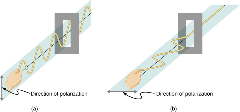
Consider the transverse waves in the form of an oscillating rope. When the oscillations of the rope are in a vertical plane, it is said to the vertically polarized. Similarly, when it is oscillating in a horizontal plane, it is horizontally polarized.
EM waves
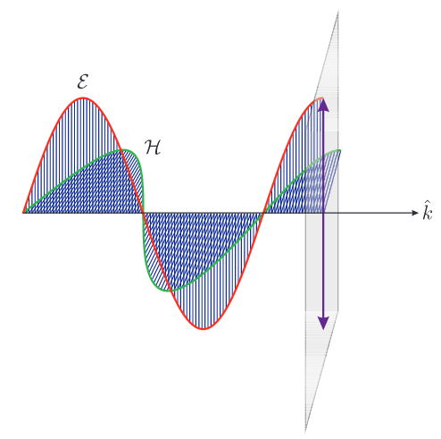
For an EM wave, the direction of polarization is defined as the direction parallel to the electric field (\[\mathcal{E}\]). The reason behind it being the direction of electric field is actually a semi-arbitrary choice. This is partly due to in practice, we more commonly sense EM waves by their electric fields rather than their magnetic fields.
Unpolarized waves
The Sun and many light sources produce EM waves (light is an EM wave) that are randomly polarized. Such light is said to be unpolarized as it is composed of many waves with all possible directions of polarization.
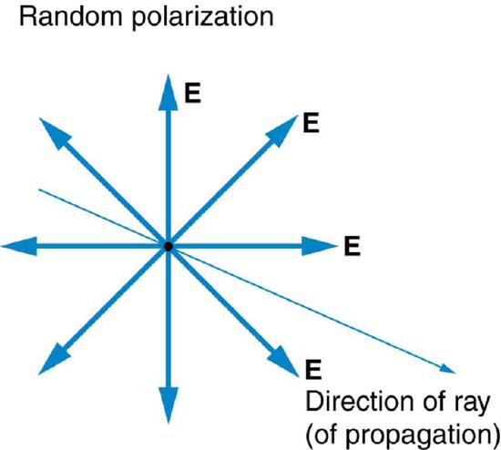
The thin arrow represents an unpolarized light ray while the bold arrows represent the direction of polarization of the individual waves composing the ray.
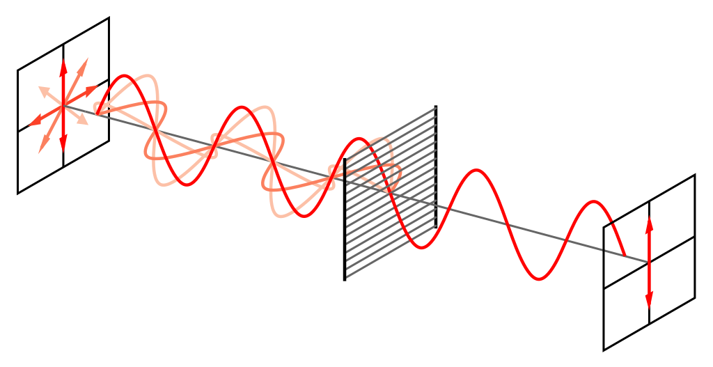
One could polarize this unpolarized light ray with a polarizer, which is sort of a filter for light. When a light ray with random polarization passes through the polarizing slit, only the individual light waves with a specific polarization can pass through, while the light waves of other polarizations are blocked. This allows us to filter a beam of light of undefined or mixed polarization into a beam of well-defined polarization, known as polarized light. The image above showcases a wire-grid polarizer that absorbs and reflects waves parallel to its wires.
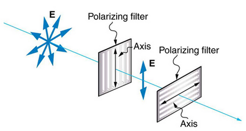
If we place two polarizers who axis are perpendicular to each other, no light will be able to pass through. However, if we were to insert a third filter whose axis are not parallel to either of the polarizers in between the two, some light will actually be able to pass through.
Malus's law
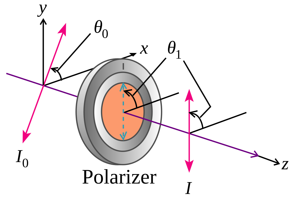
Let us call the angle between the direction of polarization and the axis of a filter \[\theta_{i}\], where \[\theta_{i}=\theta_{1}-\theta_{0}\]. If the electric field has an amplitude, say \[E\], the transmitted part of the wave will have an amplitude \[E\cos\theta\]. Since the intensity of a wave is proportional its amplitude squared, i.e. \[I\propto A^{2}\], the intensity of the transmitted wave is related to the incident wave by \[I=I_{0}\cos^{2}\theta_{i}\].
Linear polarization
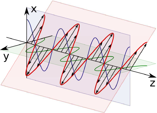
The diagram above shows linear polarization where the angle \[\phi=-\frac{\pi}{4}\].
Linear polarization arises when the source of the wave is linearly polarized. A wave is said to exhibit linear polarization if the direction of the electric field vector does not vary with either time or position.
A common example is the wave radiated by a straight wire antenna, such as a dipole or a monopole. Linear polarization may also be created by passing a plane wave through a polarizer, this is particularly common at optical frequencies.
Circular polarization
Another commonly encountered alternative to linear polarization is circular polarization.
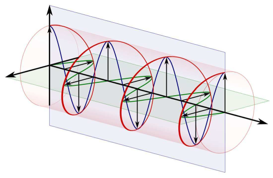
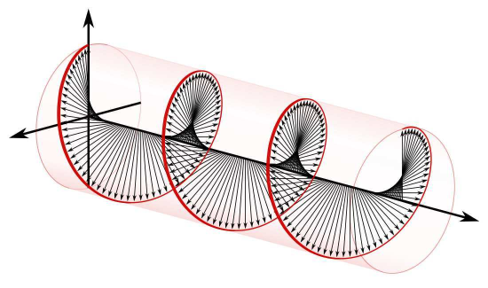
The diagrams above show left circular polarization (left) and right circular polarization (right).
Light which is polarized circularly consists of two perpendicular electromagnetic waves. In this case, show to the right, there are two electric fields which are perpendicular to each other (the illustration does not show the magnetic fields). These electric fields have equal amplitude but have a phase shift of 90 degrees. This creates an electric field vector which moves in a circle as the wave travels.
Creating circularly polarized light
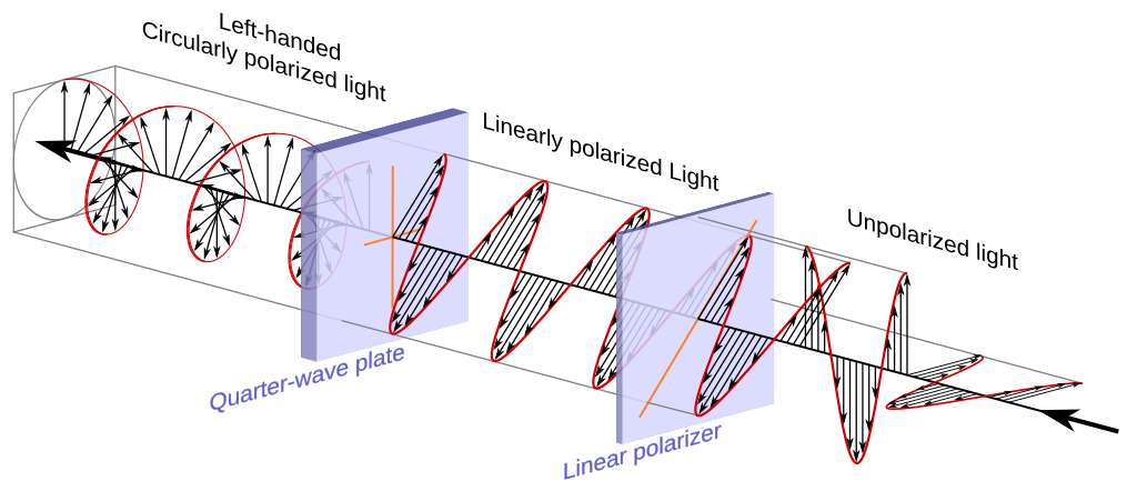
The most common way involves a linear polarizer followed by a quarter-wave plate. The transmission axis of the linear polarizer needs to be 45 degrees relative to both the fast and slow axes of the quarter-wave plate.
Elliptical polarization
Elliptical polarization is very similar to circular polarization. The difference is that the electric fields do not have equal amplitudes. Therefore the electric field vector creates an elliptical shape as the wave progresses due to the changing magnitude and direction.